-40%
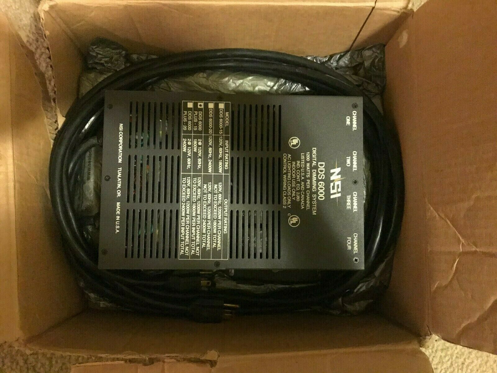
NSI DDS 6000 Dimmer Plus-15
$ 79.2
- Description
- Size Guide
Description
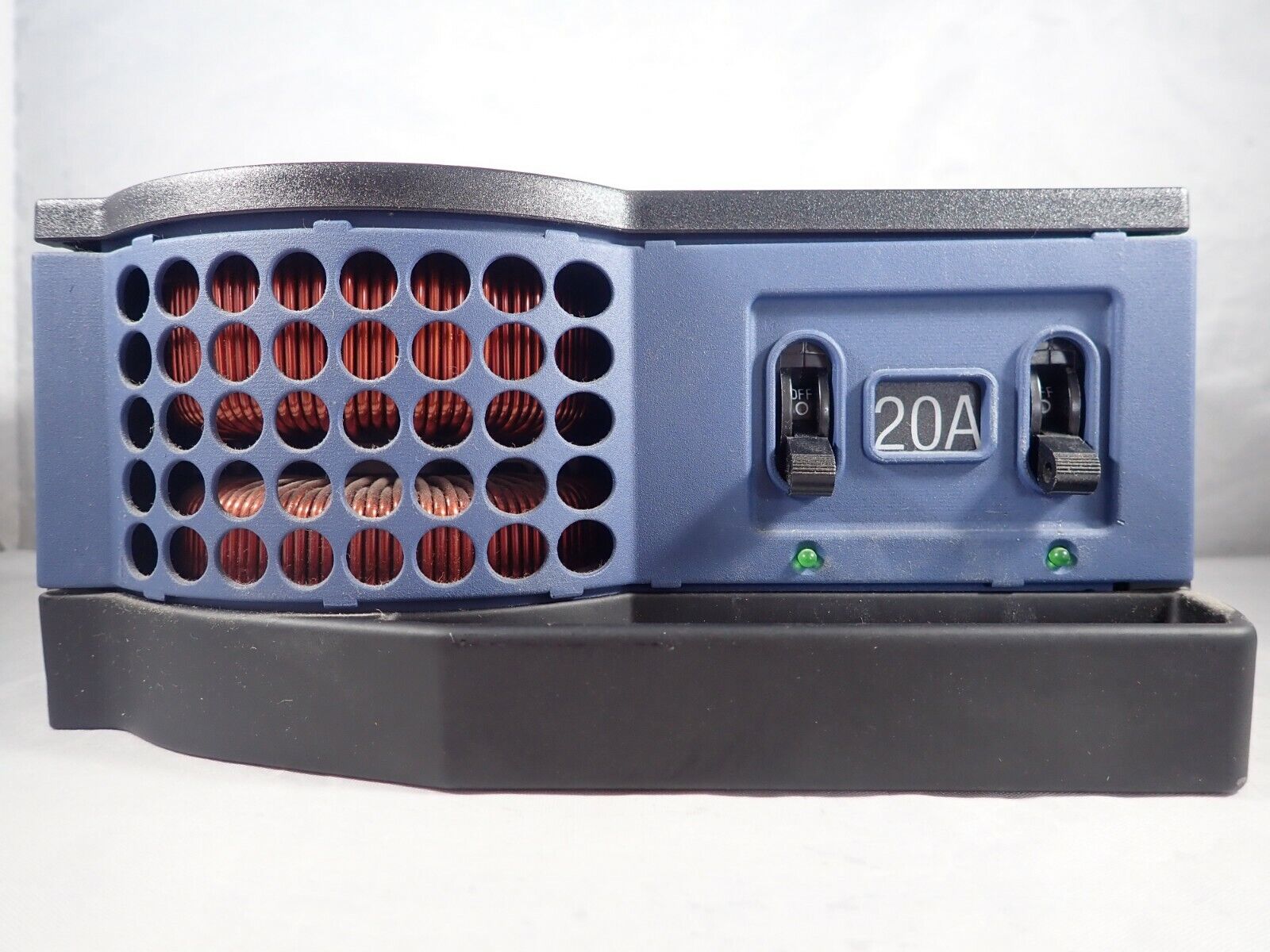
TheNSI DDS 6000
represents a key part of a state of the art, integrated lighting control system. These dimmers may operate in a "stand alone" mode for automated lighting of displays or may be combined with an NSI memory lighting console for total lighting control. The DDS 6000 provides four channels of 1200 watts each. This dimmer is designed for portable or permanent use for entertainment or display lighting. Several DDS dimmer packs may be combined for more channels of lighting.
Output capacity:
1200 Watts per channel.
Input Power:
20 VAC 3600 Watts max (two power sources)
Dimmer control system:
Microprocessor digital phase control dimming or zero-crossing relay mode.
Output Connections:
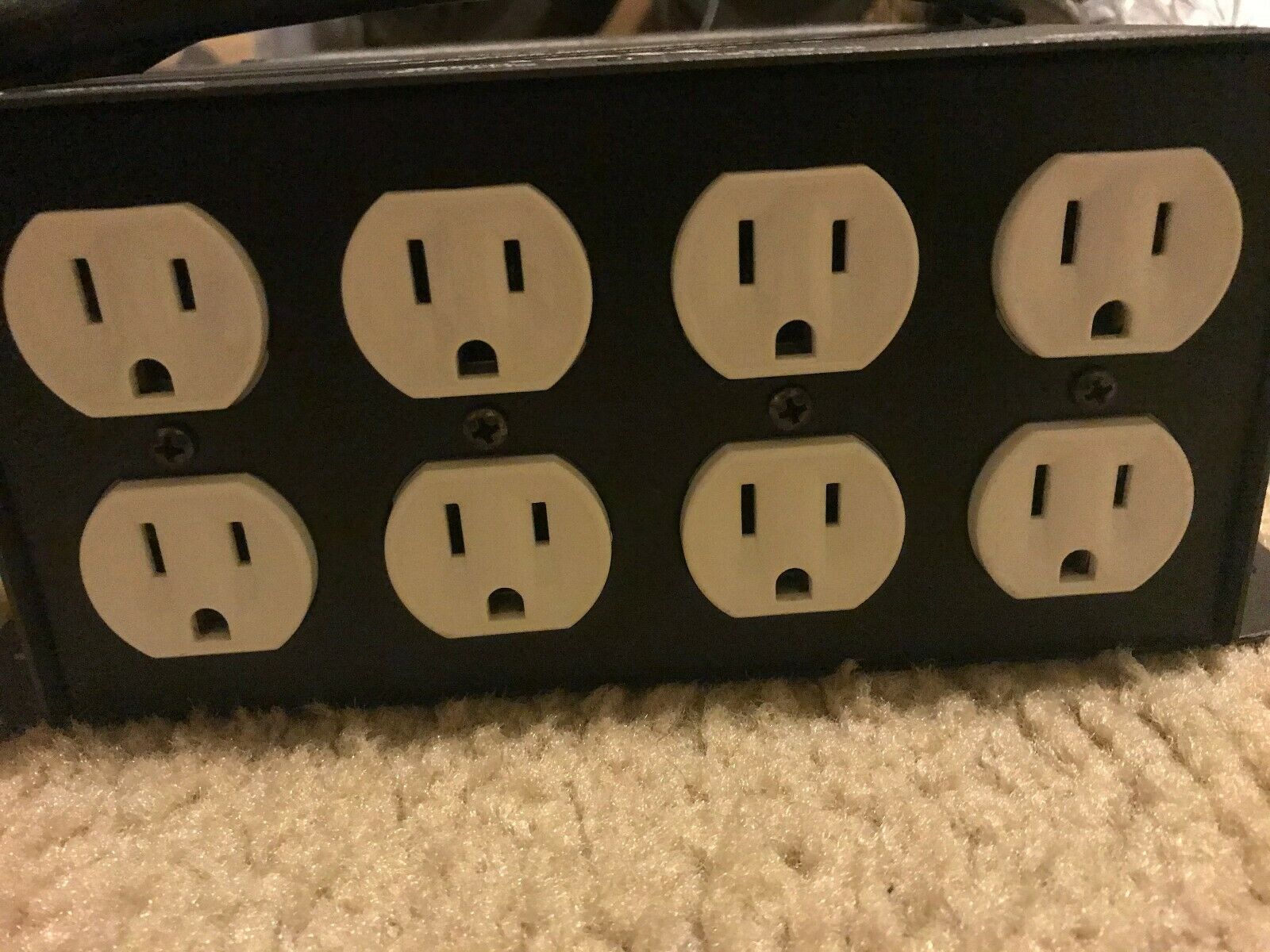
2 NEMA 5-15 outlets per channel. Screw terminals optional
Cooling System:
Passive external aluminum heatsinks.
Ambient Temperature:
100 degree F Maximum.
Load Type:
AC lighting loads only
Enclosure Type:
For indoor use only
MOUNTING:
The NSI DDS 6000 dimmer pack is designed to be mounted VERTICALLY. Each dimmer pack is provided with two mounting flanges or ears designed for securing to the center of truss bars or attaching to other vertical surfaces. Since the DDS 6000 depends upon convection cooling, room air flow must be insured. Keep the air vents located on front and each side of the dimmer pack clear of dust or any obstructions. In order for the unit to cool properly the control receptacles must be oriented toward the floor. If several units are to be operated in a small enclosed room, adequate ventilation must be provided to prevent the room temperature from exceeding 100 degrees Fahrenheit A
AC Input:
Conduit containing line conductors enters pack through one of the knock-outs in the top end. The two 20A, 120V, 60HZ, 2 wire line circuits, A and B, are terminated to their respective terminals labeled Line and Line N. The terminals accept wire sizes 22-8 AWG CU and have a torque rating of 8 in-lbs. Line equipment grounding conductor, if a wire, terminates to the lug labeled Gnd. The ground lug accepts wire size 14-6 AWG CU and has a torque rating of 35 in-lbs. (14-10 AWG), 40 in-lbs. (8 AWG), and 45 in-lbs. (6 AWG).
AC Output:
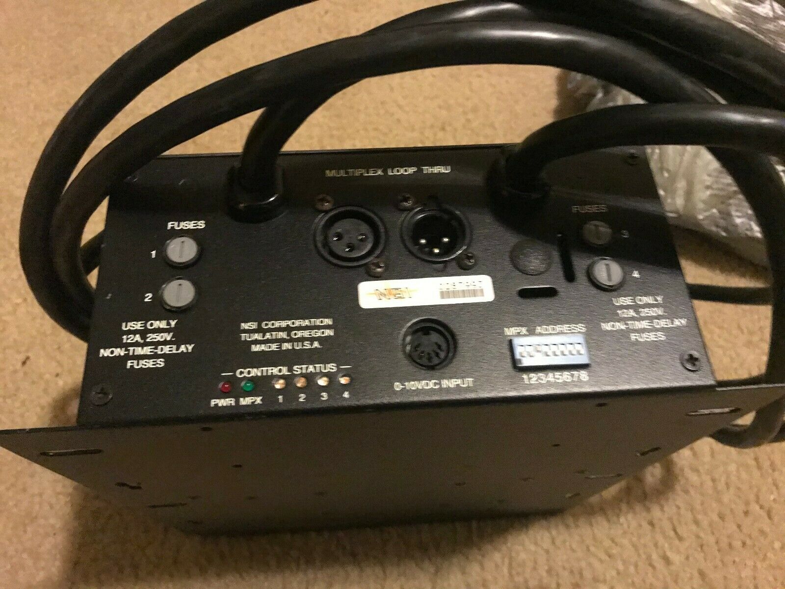
Conduit containing load conductors enters pack through on of the knock-outs in the top end. The four 1200W max, 120V, 2 wire load circuits, 1 through 4, are terminated to their respective terminals labeled Load and Load N. Circuits 1 and 2 are supplied from input A, and circuits 3 and 4 from input B. The control power supply is also supplied by input A. Terminal rating are the same as indicated above for line terminals. MICROPLEX MULTIPLEX CONTROL WIRING. Microplex is the control protocol used on most NSI lighting consoles. This system uses a single three conductor cable to transmit up to 128 channels of dimmer control. For short distances (50 feet or less) a standard microphone cable may be used to carry both the control signal and the DC power source for NSI control consoles. Longer distances may be accommodated with 18 gauge or better cable to reduce voltage losses of the power supply. Connect the Microplex control cable to either of the three pin XLR jacks. Since both jacks are wired in parallel, another control cable may connected between the remaining jack and another dimmer pack. Many dimmer packs may be "daisy chained" together in this manner. Be sure to set the Channel Address dip switch as required
DMX-512 MULTIPLEX CONTROL WIRING:
NSI DDS Dimmer products can be converted from Microplex to DMX 512 digital multiplex with a simple kit available from your dealer. DMX-512 is the preferred type of control wiring when many dimmer channels are used, because of the high update rate and the resistance to interference. It is recommended in locations subject to electrical noise. DMX-512 only requires 3 wires to transmit lighting levels for as many as 512 dimmer channels. Most of the NSI lighting control consoles can optionally use this interface.
Connect the DMX 512 cable from the control console to the male input connector. Another cable may be connected from the female connector to the male connector on another pack. Many dimmer packs may be "daisy chained" connect together in this manner.
Be sure to set the Channel Address dip switch as required (see DIP SWITCH SETTINGS). LED INDICATORS The front panel indicator LEDs indicate the status of the dimmer. · RED - Indicates the firing card is receiving DC power. · GREEN - Steady indicates a multiplex control signal is being received. · YELLOW - Indicates a respective dimmer channel is active and the LED indicates relative intensity.
